RoboPol
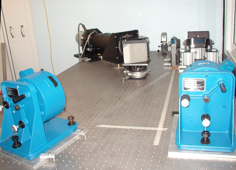
RoboPol is a specialized photopolarimeter designed specifically for the 1.3m telescope at Skinakas and commissioned in the spring of 2013. It was conceived, designed, and developed by the RoboPol Collaboration, which is comprised of the University of Crete and the Foundation for Research and Technology – Hellas in Greece, the California Institute of Technology in the United States, the Max-Planck Institute for Radioastronomy in Bonn, Germany, the Nicolaus Copernicus University in Poland, and the Inter-University Centre for Astronomy and Astrophysics (IUCAA), in Pune, India.
RoboPol was originally used to study the polarization of visible radiation from >100 blazars with intense gamma rays, which allows the testing of structure and radiation patterns by jets emanating from super-massive black holes. Subsequently, RoboPol has been extensively used for other research problems, including mapping the magnetic fields of molecular clouds in our Galaxy.
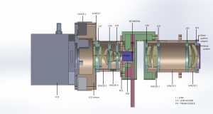
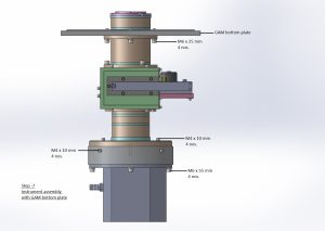
RoboPol was designed with high observing efficiency and automated operation as prime goals. It uses no moving parts other than the filter wheel. Instead, a combination of halfwave plates and Wollaston prisms are used to separate photons with orthogonal linear polarizations retard them, and simultaneously produce four images on the CCD detector for each source in the focal plane. The photon counts in each “spot” are used to calculate the Stokes parameters of linear polarization. This novel, 4-channel design eliminates the need for multiple exposures with different halfwave plate positions, thus avoiding unmeasurable, dominant systematic errors due to sky changes between measurements. A mask in the telescope focal plane prevents unwanted photons from the nearby sky and sources from overlapping with the central target on the CCD, further increasing the sensitivity of the instrument. Its large, 13’x13’ field of view allows relative photometry using standard catalogs (USNO, PTF, etc.), and the polarimetric mapping of large regions in the sky.
More information including the science results obtained with the instrument is available in the web site of RoboPol.
Near Infrared Camera
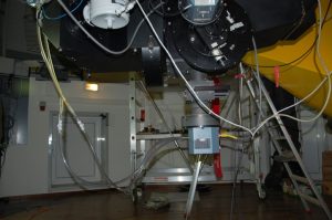
In 2006 a wide field near-infrared camera was commissioned on the 1.3m telescope. The camera consists of a 1024×1024 HgCdTe Focal Plane Array, with 18.5×18.5μm pixel size, made by Rockwell Science Center, Inc. The optical system, displayed here, is a modified Offner design with a resulting imaging resolution of 0.38arcsecs per pixel, and a 6.5arcmin x 6.5arcmin field of view. The picture below displays the dewar of the camera mounted on the 1.3m telescope, as well as the rack of the external electronics box.
The system is sensitive in the spectral range between 1.0 – 2.4 μm and has two filter wheels. A set of broadband filters (J 1.250μm, H 1.635μm, Ks 2.150μm) is mounted on Filter Wheel 2, and a set of narrowband filters ([FeII] 1.644μm, H2(1-0) 2.122μm, H2(1-0 off) 2.144μm, Br-γ 2.166μm, CO(2-0 bh) 2.295μm) is on Filter Wheel 1.
The details of the near-IR filters are the following
Description | Center Wavelength/ FWHM | Filter Wheel |
| [FeII] | 1644/17 nm | Filter Wheel 1 |
| H2(1-0) | 2122/22 nm | Filter Wheel 1 |
| H2(1-0 off) | 2144/22 nm | Filter Wheel 1 |
| Brγ | 2166/22 nm | Filter Wheel 1 |
| CO(2-0 bh) | 2295/231 nm | Filter Wheel 1 |
| J | 1250/160 nm | Filter Wheel 2 |
| H | 1635/290 nm | Filter Wheel 2 |
| Ks | 2150/320 nm | Filter Wheel 2 |
Optical Cameras
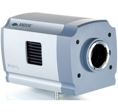
Two (2) ANDOR iKon-L 936
2048 x 2048 CCD array, 13.5μm square pixels, cooling down to -100oC.
Model BEX2-DD, Back Illuminated CCD, Deep Depletion with fringe suppression, extended range dual AR coating.
Quantum Efficiency curves for ikon_L by manufacturer are shown here.
Performance as indicated by the manufacturer is here.
- FOV 9.5arcmin square @ 130 cm Telescope
ANDOR DZ436
2048 x 2048 CCD array, 13.5μm square pixels, cooling down to -75oC.
- FOV 9.5arcmin square @ 130 cm Telescope
- FOV 1.66o square @ 30 cm Telescope
The official characteristics of the camera are available here, and the performance as indicated by the manufacturer is here. The measurements at the lab of Skinakas Observatory are:
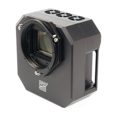
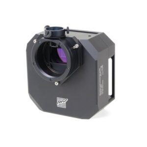
MORAVIAN C5A-150
14208 x 10656 resolution, IMX411 CMOS sensor, 3.76μm square pixels, with USB 3.0 interface.
- FOV 25.8 x 19.4 arcmin @ 1.0m telescope
- Back-illuminated design and very low dark current.
- 1-s download speed at full resolution
- Equipped with GPS receiver module
- Regulated thermoelectric cooling is capable to cool the CMOS sensor up to 45 °C below ambient temperature. The Peltier hot side is cooled by fans.
The full User’s Guide from the manufacturer can be found here
MORAVIAN C3-26000 PRO
6276 x 4176 resolution, IMX571 CMOS sensor, 3.76μm square pixels, with USB 3.0 interface.
- FOV 11.4 x 7.6 arcmin @ 1.0m telescope
- Back-illuminated design and very low dark current.
- 0.22 seconds download speed at full resolution
- Regulated thermoelectric cooling is capable to cool the CMOS sensor from 40 to 45 °C below ambient temperature. The Peltier hot side is cooled by fans.
The full User’s Guide from the manufacturer can be found here
Optical Filters
Standard Johnson-Cousins/Bessell filters
List of Strömgren filters
| Description | Central Wavelength (Å) | FWHM (Å) | Peak Transmission (%) | Diameter (mm) | Thickness (mm) | Manufacturer |
| u | 3500 | 330 | 57 | Custom Scient. | ||
| v | 4110 | 170 | 67 | Custom Scient. | ||
| b | 4685 | 183 | 83 | Custom Scient. | ||
| y | 5493 | 235 | 84 | Custom Scient. | ||
| Hbeta wide (4869?) | 4890 | 145 | 80 | 76 | 10.2 | Omega Optical |
| Hβ narrow (4864) | 4869 | 32 | 80 | 75.8 | 6 | Spectrofilm |
List of redshifted Hα filters
| Description | Central Wavelength (Å) | FWHM (Å) | Peak Transmission (%) | Diameter (mm) | Thickness (mm) | Manufacturer |
| Hα at 6563 | 6552.8 | 64.1 | 87.9 | 100 | 5 | Omega Optical |
| Hα at 6563 | 6595.1 | 55.3 | 81.0 | 100 | 5 | Omega Optical |
| Hα at 6563 | 6619.0 | 62.5 | 88.9 | 100 | 5 | Omega Optical |
| Hα at 6563 | 6651.2 | 57.7 | 87.2 | 100 | 5 | Omega Optical |
| Hα at 6563 | 6681.8 | 58.9 | 90.1 | 100 | 5 | Omega Optical |
| Hα at 6563 | 6726.0 | 57.7 | 81.5 | 100 | 5 | Omega Optical |
| Hα at 6760 | 6753.0 | 62.5 | 84.8 | 100 | 5 | Omega Optical |
List of interference filters
| Description | Center Wavelength (Å) | FWHM (Å) | Peak Transmission (%) | Refraction Index | Diameter (mm) | Thickness (mm) | Weight (gr) | Manuf |
| [OII]3727 | 3727 | 25 | 60 | 2 | Custom Sc. | |||
| [OIII]4363 | 4363 | 10 | 35 | 2 | 75.8 | 6.6 | 80 | Omega |
| HeII4696 | 4687 | 20 | 46 | 2 | 75.8 | 5.8 | 70 | Omega |
| Hβ4861 | 4864 | 28 | 65 | 2.1 | 76 | 10.2 | 105 | Spectrofilm |
| Hβ4861 | 4870 | 28 | 97 | 76 | 5 | Asahi | ||
| [OIII]5007 | 5010 | 28 | 63 | 2.1 | 76 | 10.2 | 105 | Spectrofilm |
| [NII]5755 | 5755 | 10 | 52 | 2 | 75.8 | 6.6 | 80 | Omega |
| HeI5876 | 5877 | 20 | 54 | 2 | 75.8 | 5.8 | 70 | Omega |
| Hα6563 | 6563 | 10 | 52 | 2 | 75.8 | 6.6 | 80 | Omega |
| Hα+[NII] | 6575 | 20 | 48 | 2 | 75.8 | 5.8 | 70 | Omega |
| Hα+[NII] | 6570 | 75 | 80 | 2.1 | 76 | 10.5 | 105 | Spectrofilm |
| Hα+[NII] | 6582 | 80 | 99 | 76 | 5 | Asahi | ||
| [NII] | 6584 | 20 | 60 | 2 | 75.8 | 5 | – | Omega |
| [SII]6716 | 6716 | 10 | 47 | 2 | 75.8 | 6.6 | 80 | Omega |
| [SII]6720 | 6720 | 27 | 80 | 2.1 | 76 | 6.3 | 70 | Spectrofilm |
| [SII]6720 | 6730 | 32 | 99 | 76 | 5 | Asahi | ||
| [SII]6731 | 6731 | 10 | 57 | 2 | 75.8 | 6.6 | 80 | Omega |
| [SII]6735 | 6735 | 30 | 48 | 2 | 76 | 5.75 | 70 | Omega |
| [SIII] | 9069 | 20 | 70 | 2 | 75.8 | – | – | Omega |
| Continuum | 6096 | 134 | – | – | 76 | 6.5 | 70 | Spectrofilm |
Notes
Peak Trans: Peak Filter Transmission
RI: Filter Refraction Index
Focal Reducer - Optical Slit Spectrograph
A Focal Reducer is mounted to the 1.3m telescope. The Focal Reducer can be used in two different configurations:
1. In the imaging mode the focal length of the telescope is reduced by a factor of 1.87, enlarging by the same factor the imaged area of the sky on the CCD. A Filter Wheel with 6 filter positions is integrated to the Focal Reducer.
View the list with available filters here excluding those of 100 mm diameter.
2. In the spectroscopy mode a reflection grating is introduced in the collimator path. Using different gratings, resolutions ranging from 0.57Å/pixel to 4Å/pixel are achievable with a 13.5μm 2048×2048 pixel Ikon-L CCD camera.
GRATINGS FOR THE FOCAL REDUCER
| Lines/mm | Blaze Wavelength (nm) | Wavelength in1.order for max. Intensity | Dispersion (Å/mm) | Mounted |
| 3600 | 250 | 231 | 25.41 | No |
| 2400 | 430 | 397.3 | 37.8 | Yes |
| 1302 | 550 | 508.1 | 70.44 | Yes |
| 1302 | 480 | 443.5 | 70.27 | Yes |
| 1200 | 700 | 646.7 | 76.39 | Yes |
| 651 | 530 | 489.7 | 137.6 | Yes |
| 600 | 750 | 692.9 | 150.8 | Yes |
| 600 | 500 | 461.9 | 148.4 | Yes |
| 325.5 | 550 | 508.1 | 269.0 | No |
| 325.5 | 430 | 397.3 | 267.3 | Yes |
| 162.75 | 500 | 461.9 | 529.1 | No |
Echelle Spectrograph (not operational)
The Echelle Spectrograph was a fiber-fed spectrograph mounted on optical bench in the ground floor of the 1.3m telescope building inside an isolated room.
The main refraction element is the echelle grating with 31.6 grooves/mm with a ruled area of 102 mm x 206 mm while the cross-dispersion is done by two LF5 prisms.
The optical layout can be seen here.
The optical design is a white-pupil arrangement with measured resolution R~19000 with 100μm fiber, while expect of ~38000 with the 50μm fiber.
The CCD was mounted is a 2k x 2k, 13.5μm pixel, Peltier cooled camera (Andor DW436) whose spectral coverage is shown here.
The Echelle Spectrograph is not offered for observations.
OPTIMA (not operational)
OPTIMA (Optical Pulsar TIMing Analyzer), a high-speed photoncounter was a guest instrument of the 1.3m telescope, provided by the Max Planck Institute for Extraterrestrial Physics (Germany).
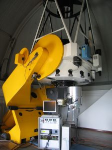
OPTIMA, seen on the photo to the right mounted on the telescope, was regularly available at Skinakas Observatory for a period of two to three months each year, until it was decomissioned in 2013.

